

Over the past last month or so, I have been working on creating the hardware and the software needed to be able to boot/reboot/hard reboot my computers at home. The reason I need this is that I am going away for a few months, away from my computers, and I would like to be able to keep on reverse engineering nvidia’s ptherm.
A possible software-only solution is to use Wake-On-Lan to boot up the computer remotely, ssh to connect to the computer, grub-reboot to select the kernel to boot on at the next reboot and finally, the watchdog to reboot the computer when it crashes. If it seems to you like a pain to use, I definitely agree!
So, a hardware-based solution seems more interesting! The standard solution to solve this issue is called IPMI. The interesting features are:
- Being able to cut the power down and put it back up again;
- Read back some of the state (Power & disk LEDs for instance);
- Having a serial console.
However, I don’t have an IPMI-ready motherboard as they are usually used on servers. I thus decided to make myself an equivalent. The only thing that was worrying me was that I had to be able to control that from the internet. So, one machine had to be up and running! I decided to buy a Raspberry Pi as it was the cheapest and lowest-power consumption computer I could get with an ethernet port and a few General Purpose Input/Output (GPIO).
Using those GPIOs, I can control a custom-made circuit board to cut the power, press the power switch and read the power led state but the real question was about the user interface to wrap those GPIOs. I decided to make a web-based user interface because it was more demo-able and also could be updated in real time for displaying logs and the power LED state.
Writing the web interface
I choose to use Wt as it is a C++ widget-oriented web toolkit. This means that pushing updates is very simple (handled by the toolkit) and accessing the GPIOs can be done with a native library, namely wiringPi. The reason I choose Wt was because I loved it when I used it in my Wt comments project.
There isn’t much to say about the code appart from the fact it is located on gitorious under the name wt-rpm. Here is how the result looks like:

The electronics
With the software done and out of the way, it was time to work on the electronics part that would take the RaspberryPi’s GPIOs and would control the motherboard / ATX power supply.
My main design goal was that I didn’t want to fry my RPi no matter how stupid I was with the GPIOs. Indeed, the GPIOs are apparently very sensitive and shouldn’t draw more than 3mA when in output mode. We discussed about that at the Bordeaux hackerspace (LabX) and we agreed that the best solution is to use opto-isolators.
I also wanted the RaspberryPi to control as many computers as needed. So I decided to have all the opto-isolation on the Raspberry Pi side and all the heavy lifting on the pc side. This means there would be N+1 boards for N PCs. I was then advised to use an ethernet cables to connect all circuits together.
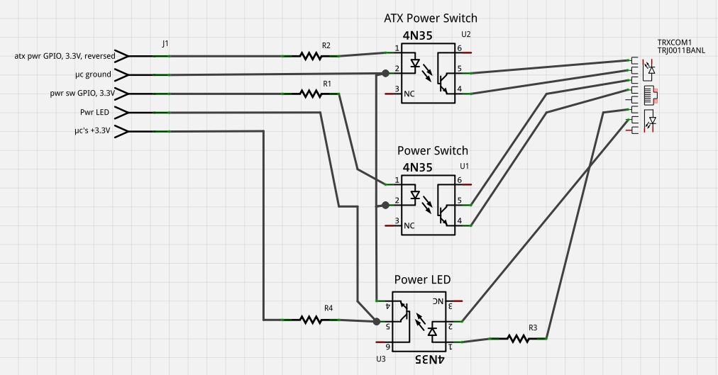
Here is the designed electronics circuit:
Cutting the computer’s power
In order to cut the computer’s power, I first thought about using a relay to cut the power before the ATX power supply. The problem with that was that I would have needed another power supply to command the relay as it usually needs a voltage of 12 to 24V and consumes a lot of power (with regards to what a USB port can actually provide).
Someone at the LabX made me look into the possibility of cutting the power after the ATX power supply. For those of you who don’t know, when plugged, the PSU delivers a +5V voltage that allows the motherboard and some peripherals to operate even when the computer is shut down (purple wire). When the motherboard wants to boot up, it shorts the green wire with the ground. This is the signal for the ATX power supply to supplying voltage on the other pins. The computer then boots up.
The idea was to be able to cut the green wire so as it wouldn’t be shorted anymore and would result in computer not being supplied with power. If the computer was already booted, it would come to a stop instantly.
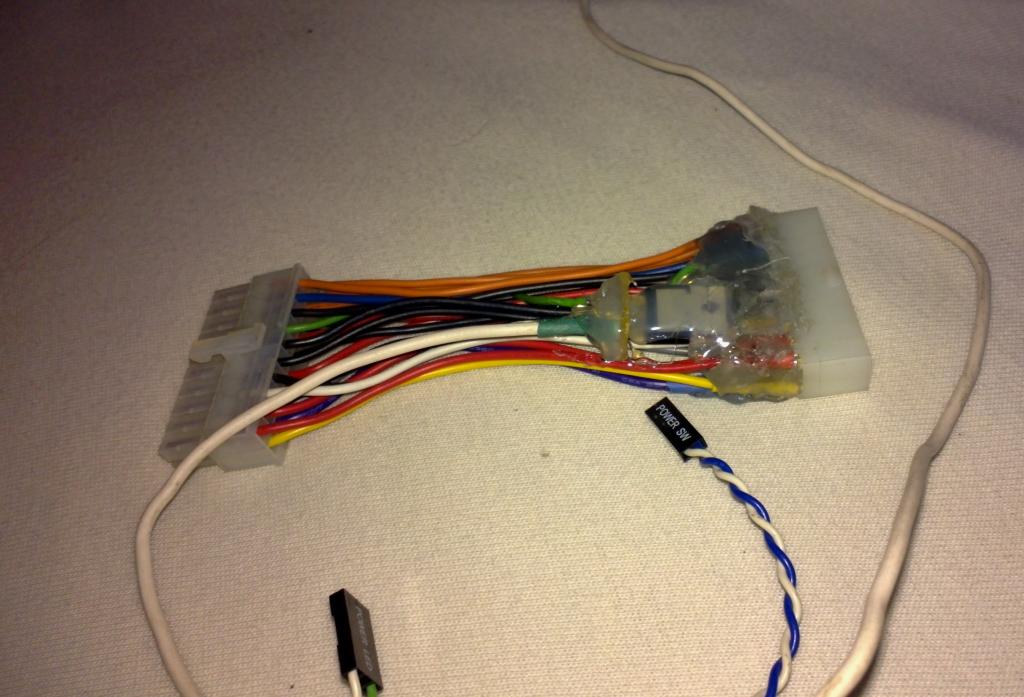
As I didn’t want to fiddle with my ATX power supplies, I created an ATX extension cord with a MOSFET (a voltage-commanded transistor) that would let through the current in the green wire but, when the gate would be forced to 0V, would cut the power supply. To let through the current by default, I just put a pull-up resistor (10 kOhm) at the gate of the MOSFET. The gate is then connected to the output of the opto-isolator that would tie it to the ground when needed.
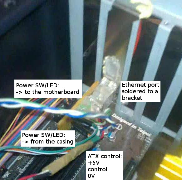
Here are some pictures of how it looks:

The ATX connector pinout figure has been made by Lazar Rozenblat. Check out his awesome page on ATX power supplies.
Pressing the power switch button
This part is more straightforward. To electronically act as the main power switch, we only need to short the two power SW pins found on the motherboard. This can be done with a simple transistor,
As I also wanted to be able to power-up the computer by pressing the actual button, I decided to put the button and the opto-isolator in parallel.
Reading out the power LED’s state
There is nothing fancy here. The power LED pins are redirected to the input part of the opto-isolator. I also put in parallel the original power LED. That’s not a proper solution because by doing so, the real power LED receives mA than it should. However, since the opto-isolator’s internal LED only draws a few mA, it seems to work fine.
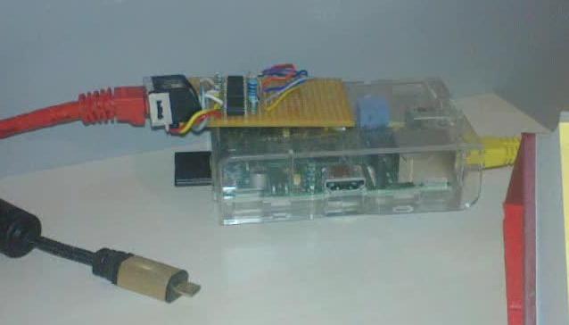
The final circuit and its assembly
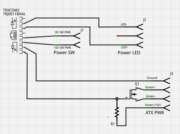
So, here is how the final circuit looks like:
I decided to mount it on a bracket so as it wouldn’t float around in the computer. I both soldered and hot-glued the ethernet connector to the bracket to make it as sturdy as possible. Soldering was hard as the bracket was cooling the soldering iron but after putting the temperature to 450°C and being a bit patient, I managed to get a proper soldering.
The final circuit (a close version of it) can be found in the repository of wt-rpm, as two separate fritzing projects.
The (necessary) video
Adding a serial console
Now that we can force a computer on and off, we need a way to select which kernel should be booted and be able to debug issues that could happen before ssh is up and running. For that, I decided to use the serial port of my motherboards.
I found on ebay some very cheap RS-232-to-USB converters, for about 3€ each. The only problem with them is that they use the standard db-9 connector and none of my motherboards actually had one. Instead, they had a connector at the bottom exposing the different pins. So I made a very simple null modem cable (just used the ground, RX and TX) that would connect on the motherboard’s exposed pins and connect them to the adaptor.
I got it to work quite reliably, however, from time to time, grubs really looks garbelled, I wonder if it is due to the very cheapness of the adaptors or if it is a problem due to the fact I have no hardware hand-shacking on my cables. When I come back, I’ll try to have a look at it!
That’s all folks!